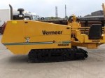
CÔNG NGHỆ KHOAN NGANG ĐỊNH HƯỚNG HDD
CÔNG NGHỆ KHOAN NGANG ĐỊNH HƯỚNG HDD
Ngày đăng: 03-03-2021
1,710 lượt xem
TÓM TẮT CÔNG NGHỆ KHOAN NGANG ĐỊNH HƯỚNG HDD
1 - SITE INVESTIGATIONS AND DESIGN
2 - PILOT HOLE DRILLING
3 - HOLE ENLARGING
4 - PULL BACK
1 - SITE INVESTIGATIONS AND DESIGN (SUMMARY)
Project design starts with the gathering of necessary information. This information includes the site survey, including the locations of existing pipelines and services and a geotechnical site investigation.
The geotechnical investigation’s results will determine the tools that will be used in drilling the crossing.
The work site is visiting during the design stage to assess existing obstacles that may affect the drilling process.
2 - PILOT HOLE DRILLING (SUMMARY)
The pilot hole is drilled from the entry point to the exit point following the profile and alignment previously designed. The selection of the drilling tools and the drilling rig spread to be used will be determined based largely on the results of the geotechnical investigations.
The “jetting” process is used to drill soft soils. This process consists of pumping drilling fluid through the drill pipe to a jet bit.
During the pilot hole drilling, a directional guidance system is used to navigate the pilot hole along it pre-designed profile.. the “surface guided” system can be used in this job.
3 - HOLE ENLARGING (SUMMARY)
In small diameter crossings, the pipeline may be directly installed in the hole once the pilot hole is completed. However, in most cases, pilot hole enlarging will be necessary- this process is known as “pre-reaming”. Pre-reaming is required to provide an annular space large enough that the pipeline can be installed in the drilled crossing. According to the desired final diameter and the soil conditions, the pre-reaming procedure may include one or more stages. Generally, the “rule of thumb” is that the final diameter of the drilled hole should be 30% larger than the diameter of the pipe to be installed. There are different types of reaming tools suited to the different types of soil conditions. The type of tool selected and the soil conditions it is being used in will have a direct effect on the pre-reaming procedure. It is important to combine adequate tooling with the correct drilling fluid characteristics and pump rates to build stable side walls, remove cuttings, and maintain an open hole suitable for the installation of the pipeline (the pullback).
For the D500 river crossing project, we should use the following Back reamer for hole enlargement.
- Wing cutter 12’’
- Flutted reamer: 12’’, 16’’, 24”, 30”
- Barrel Back reamer: 30”
- Swivel 45 Ton capacity.
Drilling Fluid
Generally, the drilling fluid is a water-based mud obtained by mixing water with a specific amount of bentonite. If necessary, small quantities of polymers may be added to the mixture. The amount of bentonite used depends on the site specific geotechnical conditions and the operation that is being performed. Drilling fluid has a series of functions that are detailed below:
Ø It produces hydraulic cutting of soil by being pumped at a high velocity through jets in the drilling tools (bits, reamers, hole openers, etc). It also powers the operation of mud motors.
Ø It establishes and maintains the drilled hole integrity (avoids collapse)
Ø It lubricates the tools and the drill pipe
Ø It carries the cuttings to the surface
Ø Because of the water condition is salty, saturated. The following water treatment agent should be used. Specifications attached:
- Main agent : Aus – Gel
- Au. Agent : XAN BORE
- Au. Agent : AMC – Pac - R
The drilling fluid function is, apart from lubricating the tool and carrying the cuttings to the surface, to keep the drill hole side walls stable to avoid collapse and prevent seepage and circulation prosses.
When the drilling fluid returns to the surface through the drilled hole, it is pumped to a cleaning system where it passes through a series of hydrocyclone shale shaker screens which separate the solid waste, leaving the fluids in a condition to be reused.
As a practical “rule of thumb”, the minimum radius of curvature in a drilled profile is 100 feet (30.5m) per diameter inch of the pipeline that will be installed.
Notwithstanding this, calculations can be undertaken based on the pipeline specification, the crossing type, the topographical and geotechnical features, and the operating conditions to determine the acceptable minimum curvature radius that will be used.
4 - PULL BACK (SUMMARY)
Once the drilled hole has been enlarged to the required diameter and cleaned adequately, the pipeline is installed. In most cases, the pipeline should be preassembled and placed on rollers prior to pullback. In the design of a crossing, it is necessary to consider the drill’s exit angle ensuring it will be acceptable and does not generate excessive stress in the pipeline during its installation in the drilled hole. If the pipeline cannot be assembled in a single string, the duration of the complete pull back procedure must be considered, including welding and x-ray or fusing (in the case of steel pipelines), given that the installation should be made with minimum stoppages. The drilling fluids that will be displaced by the pipeline during the pullback must also be carefully considered. If additional, or special, storage, may be required it should be sourced prior to starting the pullback. For the pullback, a reamer is connected to the drill pipe, which will both remove any cuttings and keep the hole’s side walls stable. Behind the reamer, a swivel is connected, which allows the drill pipe to rotate the reamer but prevents any torque from being transmitted to the product pipe. The drill pipe is pulled back to the entry point until the pipeline is fully installed. During the whole pullback procedure, drilling fluid is pumped into the hole, via the reamer, to keep it full, thus reducing friction forces on the pipeline.













Gửi bình luận của bạn